This post describes the control node implementation for a three-wheeled omni-wheeled holonomic robot to update motor direction and speed from incoming linear and angular velocities.
1 Build
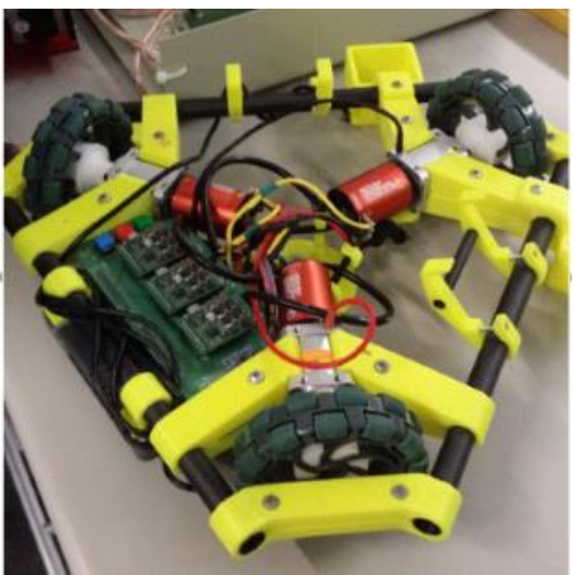
Big T is an autonomous three-wheeled omni-wheel holonomic robot with SLAM capabilities.
Big T is mounted with both exterioceptive sensors such as a mouse sensor, LIDAR and Intel RealSense and proprioceptive sensors such as IMU and encoders to capture odometry signals to inform the control algorithm.
2 Mapping Modes
There are two main mapping modes we can operate in with Big T.
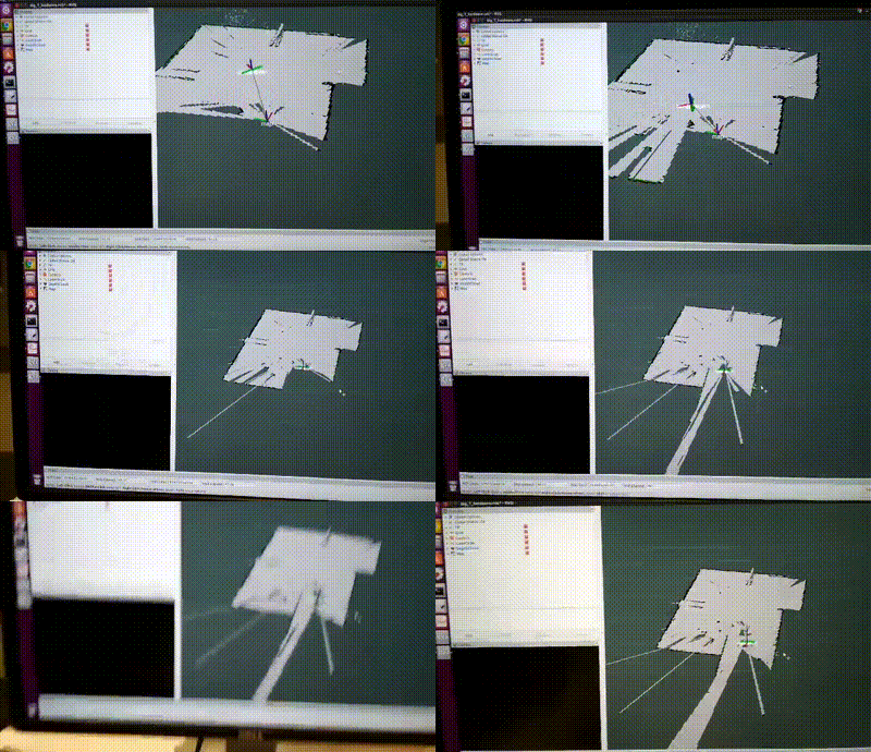
- The map of the environment is first created using Hector SLAM to simulataneously localise and map the environment and save the map. See here for reference. Hector SLAM is used in conjunction with an extended Kalman filter (EKF) to fuse wheel odometry with the IMU to create an improved odometry estimate using the
robot_pose_ekfpackage. This example below shows the robot performing autonomous SLAM to map the environment.
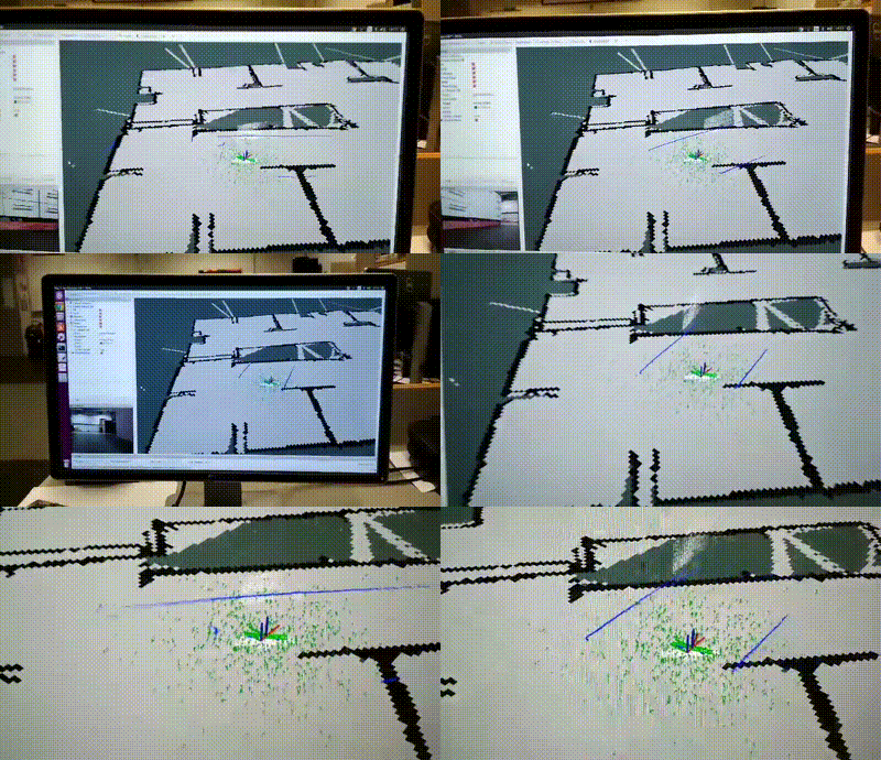
- We can test localising the robot inside the saved map using AMCL (Adaptive Monte Carlo localisation) which estimates 2D position based on particle filter. The robot’s pose is represented as a distribution of particles, where each particle represents a possible pose of the robot. It takes as input a map, LIDAR scans, and transform messages, and outputs an estimated pose. See here for reference.
3 Architecture
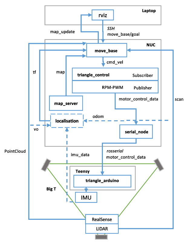
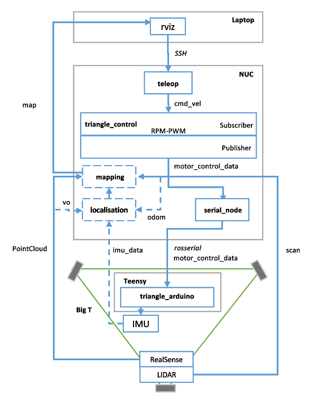
Big T can be run into two operative modes, high level block digrams are shown below:
- Autonomous Mode - this mode is often used for SLAM navigation.
- Tele-operative Mode - this mode is often used for user-controlled navigation in a saved map and also for debugging purposes.
4 Control Algorithm
The robot’s velocity commands are published on the cmd_vel topic from either theteleop_twist_keyboard node in teleop mode or move_base node in the ROS navigation stack when in SLAM node. The control node aims to translate directions in the global frame to the individual directions to each motor in three-wheeled omnidirectional robot configuration.
4.1 Imports and Global Variables
We first import our initial C++ ROS headers and instantiate our global variables from the robot’s physical characteristics.
We include the following headers:
- [
ros/ros.h] to include too headers necessary to use the most common public pieces of the ROS system. geometry_msgs/Twist.hto publish linear and angular velocities to facilitate interoperability throughout the system.geometry_msgs/Quaternion.hto publish orientation in quarternion form.sensor_msgs/Imu.hto collect sensor data message type from the IMU. The IMU noderazor_imu_9dofpublishes messages to the"imu"topic in the ROS system to be used by motion and planning algorithms such as thisrobot_pose_ekf.math.hto perform common mathmetical operations and transformations.
We then declare our ROS publishers motor_control_pub to publish the motor control signal to the wheels and imu_pub to publish and update the robot’s orientation.
#include "ros/ros.h"
#include "geometry_msgs/Twist.h"
#include "geometry_msgs/Quaternion.h"
#include "sensor_msgs/Imu.h"
#include <math.h>

float omega1, omega2, omega3; // angular velocities
float r = 0.0525; // Wheel radius (105mm/2)
float h = 0.18;   // Distance from the center of the body to the wheel (180mm)

float v_x = 0;    // Global translation speed in x (m/s)
float v_y = 0;    // Global translation speed in y (m/s)
float omega_body = 0;  // Rotational speed of the body (rad/s)
float theta = 3.1415;  // Orientation of the body (rad)

ros::Publisher motor_control_pub;
ros::Publisher imu_pub;
4.2 Main Loop
We first set up the appropriate ROS publishers and subscribers, to enable ROS signal communication between incoming sensor and output motor nodes in the ROS ecosystem.
The main loop is as follows:
- Initialises the ROS system with the node name
triangle_control. - Creates
ros::NodeHandleto interface with the ROS system. - Sets up publisher
pubto publish motor control data on themotor_control_datatopic. - Sets up
imu_subto receive IMU data onimutopic to process withimu_callbackfunction. This allows us to explicitly publish the IMU orientation to anorientationtopic. - Sets up
imu_pubto receive velocity cmmmands on thecmd_veltopic and process with thecmd_vel_callbackfunction. Thecmd_veltopic is typically used to publish velocity commands published by theteleop_twist_keyboardnode inteleopmode ormove_basenode in the ROS navigation stack when in SLAM node. - Enters infinite event loop with
ros::spin()to continuously process incoming messages on all topics to which the node is subscribed (eg.imuandcmd_vel), call the appropriate callback functions (eg.imu_callbackandcmd_vel_callback) and publish messages to the advertised topics (eg.motor_control_dataandorientation). It blocks the main thread and ensures thetriangle_controlnode runs for as long as the ROS system is active.
int main(int argc, char **argv){

	ros::init(argc, argv, "triangle_control");

	ros::NodeHandle n;

	motor_control_pub = n.advertise<geometry_msgs::Twist>("motor_control_data", 1000);

	ros::Subscriber imu_sub = n.subscribe("imu", 1000, imu_callback);

	imu_pub = n.advertise<geometry_msgs::Quaternion>("orientation", 1000);

	ros::Subscriber sub = n.subscribe("cmd_vel", 1000, cmd_vel_callback);

	ros::spin();

	return 0;

}
4.3 Converting Sensor Input to Angular Velocities
The main callback function that updates the robot’s direction is cmd_vel_callback which is subscribed to the cmd_vel topic of a data type of geometry_msgs::Twist which expresses velocity in it’s angular and linear parts. This function translates the desired linear and angular velocities of the robot into individual wheel speeds, converts those speeds to PWM signals, and determines the direction for each wheel. It then publishes these control signals to the motor_control_pub topic to update the robot direction .
void cmd_vel_callback(const geometry_msgs::Twist & msg){
	/*
		omega1	...	rotation speed of motor 1	(in rad/s)
		omega2	...	rotation speed of motor 2	(in rad/s)
		omega3	...	rotation speed of motor 3	(in rad/s)
	*/
	ROS_INFO("Msg received");

	geometry_msgs::Twist out_msg;
	v_x = msg.linear.x;
	v_y = msg.linear.y;
	omega_body = msg.angular.z;

	omega1 = 1/r * (v_x * cosf(theta) + v_y * sinf(theta) + omega_body * h);
	omega2 = 1/r * (cosf(theta) * v_y/3 -  sinf(theta) * v_x/3 +  sqrt(3) * sinf(theta) * v_y/3 +  sqrt(3) * cosf(theta) * v_x /3 + omega_body * h);
	omega3 = 1/r * (-sqrt(3) * sinf(theta) * v_y/3 + cosf(theta) * v_y/3 -  sqrt(3)  * cosf(theta) * v_x/3 - sinf(theta) * v_x/3 + omega_body * h);

	// pwm signal
	out_msg.linear.x = omega2pwm(omega1); // convert from rad/s to pwm signal
	out_msg.linear.y = omega2pwm(omega2);
	out_msg.linear.z = omega2pwm(omega3);

	// motor direction
	out_msg.angular.x = sign(omega1); // set direction bit depending on the rotation speed
	out_msg.angular.y = sign(omega2);
	out_msg.angular.z = sign(omega3);

	motor_control_pub.publish(out_msg);
}
See the following sections below for more details.
4.4 Deriving the Kinematic Equations for a Three-Wheeled Omnidirectional Robot
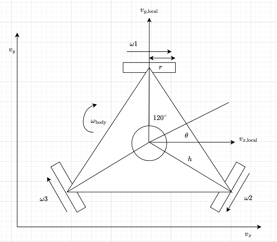
Assumptions and Setup
- Robot Configuration:
- The robot is a triangle with three holonomic wheels.
- The wheels are positioned 120 degrees apart from each other.
- Variables:
- \(v_x\): Linear velocity in the x-direction (global frame).
- \(v_y\): Linear velocity in the y-direction (global frame).
- \(\omega_\text{body}\): Rotational velocity of the robot around its center.
- \(\theta\): Orientation of the robot (angle between the robot’s frame and the global frame).
- \(r\): Radius of each wheel.
- \(h\): Distance from the center of the robot to each wheel.
Diagram
Derivation
We aim to derive the angular velocities of the three holonomic wheels \(\omega_1\), \(\omega_2\), \(\omega_3\) based on the robot’s linear velocities (\(v_x\), \(v_y\)) and rotational velocity (\(\omega_{\text{body}}\)) in the global frame, considering the robot’s orientation \(\theta\).
1. Transform Global Velocities to Local Velocities
First, we need to transform The global velocities \(v_x\) and \(v_y\) into the local frame of the robot using its orientation \(\theta\):
\[ v_{x,\text{local}} = v_x \cos(\theta) + v_y \sin(\theta) \]
\[ v_{y,\text{local}} = -v_x \sin(\theta) + v_y \cos(\theta) \]
2. Express Local Velocities and Rotational Velocity in Terms of Wheel Velocities
Each wheel contributes to the robot’s motion. The linear velocities of the wheels can be decomposed into components that affect the overall motion of the robot.
For a wheel positioned at an angle \(\alpha\) with respect to the robot’s frame: \[ \omega_{\text{wheel}} = \frac{1}{r} (v_{x,\text{local}} \cos(\alpha) + v_{y,\text{local}} \sin(\alpha) + \omega_{\text{body}} h) \]
Where \(\omega_\text{wheel}\) is the angular velocity of the wheel, and \(h\) is the distance from the center to the wheel.
3. Apply to Each Wheel
Each wheel is positioned \(120^\circ\) apart, so the angles \(\alpha\) for the three wheels are \(0^\circ\), \(120^\circ\), and \(240^\circ\).
For Wheel 1 where \(\alpha = 0^\circ\):
\[ \omega_1 = \frac{1}{r} ( v_{x,\text{local}} \cos(0) + v_{y,\text{local}} \sin(0) + \omega_{\text{body}} h ) \]
Since \(cos(0^\circ)= 1\) and \(\sin(0^\circ) = 0\):
\[ \omega_1 = \frac{1}{r} ( v_{x,\text{local}} + \omega_{\text{body}} h ) \]
Substituting the local velocities:
\[ \omega_1 = \frac{1}{r} ( v_x \cos(\theta) + v_y \sin(\theta) + \omega_{\text{body}} h ) \]
For Wheel 2 where \(\alpha = 120^\circ\):
\[ \omega_2 = \frac{1}{r} ( v_{x,\text{local}} \cos(120^\circ) + v_{y,\text{local}} \sin(120^\circ) + \omega_{\text{body}} h) \]
Since \(\cos(120^\circ) = -\frac{1}{2}\) and \(\sin(120^\circ) = \frac{\sqrt{3}}{2}\):
\[ \omega_2 = \frac{1}{r} ( v_{x,\text{local}}( -\frac{1}{2} ) + v_{y,\text{local}} ( \frac{\sqrt{3}}{2} ) + \omega_{\text{body}} h) \]
\[ \omega_2 = \frac{1}{r} ( (v_x \cos(\theta) + v_y \sin(\theta)) ( -\frac{1}{2} ) + (-v_x \sin(\theta) + v_y \cos(\theta)) ( \frac{\sqrt{3}}{2} ) + \omega_{\text{body}} h ) \]
Expanding and simplifying:
\[ \omega_2 = \frac{1}{r} ( -\frac{1}{2} v_x \cos(\theta) - \frac{1}{2} v_y \sin(\theta) + \frac{\sqrt{3}}{2} (-v_x \sin(\theta)) + \frac{\sqrt{3}}{2} v_y \cos(\theta) + \omega_{\text{body}} h ) \]
\[ \omega_2 = \frac{1}{r} ( -\frac{1}{2} v_x \cos(\theta) - \frac{1}{2} v_y \sin(\theta) - \frac{\sqrt{3}}{2} v_x \sin(\theta) + \frac{\sqrt{3}}{2} v_y \cos(\theta) + \omega_{\text{body}} h ) \]
Combining terms and simplifying further:
\[ \omega_2 = \frac{1}{r} ( \frac{\cos(\theta) v_y}{3} - \frac{\sin(\theta) v_x}{3} + \frac{\sqrt{3} \sin(\theta) v_y}{3} + \frac{\sqrt{3} \cos(\theta) v_x}{3} + \omega_{\text{body}} h ) \]
For Wheel 3 where \(\alpha = 240^\circ\):
\[ \omega_3 = \frac{1}{r} ( v_{x,\text{local}} \cos(240^\circ) + v_{y,\text{local}} \sin(240^\circ) + \omega_{\text{body}} h ) \]
Since \(\cos(240^\circ) = -\frac{1}{2}\) and \(\sin(240^\circ) = -\frac{\sqrt{3}}{2}\):
\[ \omega_3 = \frac{1}{r} ( (v_x \cos(\theta) + v_y \sin(\theta)) ( -\frac{1}{2} ) + (-v_x \sin(\theta) + v_y \cos(\theta)) ( -\frac{\sqrt{3}}{2} ) + \omega_{\text{body}} h ) \]
Expanding and simplifying:
\[ \omega_3 = \frac{1}{r} ( -\frac{1}{2} v_x \cos(\theta) - \frac{1}{2} v_y \sin(\theta) - \frac{\sqrt{3}}{2} (-v_x \sin(\theta)) - \frac{\sqrt{3}}{2} v_y \cos(\theta) + \omega_{\text{body}} h ) \]
\[ \omega_3 = \frac{1}{r} ( -\frac{1}{2} v_x \cos(\theta) - \frac{1}{2} v_y \sin(\theta) + \frac{\sqrt{3}}{2} v_x \sin(\theta) - \frac{\sqrt{3}}{2} v_y \cos(\theta) + \omega_{\text{body}} h ) \]
Combining terms and simplifying further:
\[ \omega_3 = \frac{1}{r} ( -\frac{\sqrt{3} \sin(\theta) v_y}{3} + \frac{\cos(\theta) v_y}{3} - \frac{\sqrt{3} \cos(\theta) v_x}{3} - \frac{\sin(\theta) v_x}{3} + \omega_{\text{body}} h ) \]
Final Equations
The final simplified equations for the angular velocities of the wheels are:
\[ \omega_1 = \frac{1}{r} ( v_x \cos(\theta) + v_y \sin(\theta) + \omega_{\text{body}} h ) \]
\[ \omega_2 = \frac{1}{r} ( \frac{\cos(\theta) v_y}{3} - \frac{\sin(\theta) v_x}{3} + \frac{\sqrt{3} \sin(\theta) v_y}{3} + \frac{\sqrt{3} \cos(\theta) v_x}{3} + \omega_{\text{body}} h ) \]
\[ \omega_3 = \frac{1}{r} ( -\frac{\sqrt{3} \sin(\theta) v_y}{3} + \frac{\cos(\theta) v_y}{3} - \frac{\sqrt{3} \cos(\theta) v_x}{3} - \frac{\sin(\theta) v_x}{3} + \omega_{\text{body}} h ) \]
These equations relate the global motion commands (\(v_x\), \(v_y\), \(\omega_{\text{body}}\)) to the angular velocities of the three wheels (\(\omega_1\), \(\omega_2\), \(\omega_3\)) taking into account the robot’s orientation \(\theta\), wheel radius \(r\) and distance from center to the wheels \(h\).
4.5 Converting angular velocities to PWM signal for motor control
After we’ve calculated the angular velocities in terms on radians per second (\(rad/s\)), we have to convert to a Pulse Width Modulation (PWM) signal to send updated speed and direction to the motors.
1. Angular Velocity to RPM
We first convert angular velocity (\(rad/s\)) to revolutions per minute (RPM).
We know that \(1 \space revolution=2\pi \space radians\) and \(1 \space minute = 60 \space seconds\), therefore, the conversion factor is:
\[ RPM = \omega\times(60/2\pi) \approx \omega\times 9.5493 \approx \omega\times 9.55 \]
2. Conversion from RPM to PWM
In order to measure and calibrate the relationship betwen PWM and RPM for the motor, an empirical experiment was performed in order to collect measurements and fit a linear regression model to the data.
For series of PWM signals from a low duty cycle to (eg. 10%) to high duty cycle (eg. 90%) generated using an oscilloscope, the respective RPM for the motor was recorded using a tachometer.
The resulting linear relationship is:
\[ PWM = a \times RPM + b = 2.4307 \times RPM + 36.2178 \]
This means that for every unit increase in RPM, the PWM value increases by approximately 2.4307 units, and when the RPM is zero, the PWM value starts at approximately 36.2178.
3. Handling Very Small Angular Velocities
Small angular velocities <=0.05 are ignored, to smooth noise in the signal and avoid unnecessary motor activation.
4. Linear Equation of Angular velocity to PWM
Through substituting and simplifying the equations above, we can derive the following linear relationship for converting angular velocity to PWM.
\[ PWM = 2.4307 \times RPM + 36.2178 = 2.43 \times (\omega\times 9.55) + 36.22 \]
The result is then returned as an integer PWM value which can be used to control motor speed. We later apply this to each wheel when we calculate the new angular velocities from sensor feedback. We make \(\omega\) absolute \(|\omega_{\text{wheel}}|\) in order to ensure the angular velocity is never non-negative.
5. Setting Direction Bit of Motor
The direction bit of the motor is set based on the sign of the angular velocity \(\omega_{\text{wheel}}\).
This project was executed as part of the course - ECEN430: Advanced Mechatronic Engineering 2: Intelligence and Design at Victoria University of Wellington 2018.
